
Generating Video

evergreen
Published: 2020-04-07
Last Edited: 2022-01-20
One thing I’m very interested in is computer graphics. This could be complex 3D graphics or simple 2D graphics. The idea of getting a computer to display visual data fascinates me. One fundamental part of showing visual data is interfacing with a computer monitor. This can be accomplished by generating a video signal that the monitor understands. Below I have written instructions on how an FPGA can be used to generate a video signal. I have specifically worked with the iCEBreaker FPGA but the theory contained within this should work with any FPGA or device that you can generate the appropriate timings for.
Tools
Hardware used (link for board):
- iCEBreaker FPGA
- iCEBreaker 12-Bit DVI Pmod
Software Used:
- IceStorm FPGA toolchain (follow install instructions here)
Theory
A video signal is composed of several parts, primarily the colour signals and the sync signals. For this DVI Pmod, there is also a data enable signal for the visible screen area. For the example here we are going to be generating a 640x480 60 Hz video signal. Below is a table describing the important data for our video signal.
| Pixel Clock | 25.175 MHz |
| Pixels Per Line | 800 Pixels |
| Pixels Visible Per Line | 640 Pixels |
| Horizontal Sync Front Porch Length | 16 Pixels |
| Horizontal Sync Length | 96 Pixels |
| Horizontal Sync Back Porch Length | 48 Pixels |
| Lines Per Frame | 525 Lines |
| Lines Visible Per Frame | 480 Lines |
| Vertical Front Porch Length | 10 Lines |
| Vertical Sync Length | 2 Lines |
| Vertical Back Porch Length | 33 Lines |
Sourced from http://www.tinyvga.com/vga-timing/640x480@60Hz
The data from this table raises a few questions:
- What is the Pixel Clock?
- What is the difference between “Pixels/Lines” and “Visible Pixels/Lines”?
- What is “Front Porch”, “Sync”, and “Back Porch”?
Pixel Clock
The pixel clock is a fairly straightforward idea; this is the rate at which we generate pixels. For video signal generation, the “pixel” is a fundamental building block and we count things in the number of pixels it takes up. Every time the pixel clock “ticks” we have incremented the number of pixels we have processed. So for a 640x480 video signal, a full line is 800 pixels, or 800 clock ticks. For the full 800x525 frame there is 800 ticks x 525 lines, or 420000 clock ticks. If we are running the display at 60 Hz, 420000 pixels per frame are generated 60 times per second. Therefore, 25200000 pixels or clock ticks will pass in one second. From this we can see the pixel clock frequency of 25.175 MHz is roughly equal to 25200000 clock ticks. There is a small deviance from the “true” values here, but monitors are flexible enough to accept this video signal (my monitor reports it as 640x480@60Hz), and all information I can find online says that 25.175 MHz is the value you want to use. Later on we will see that the pixel clock is not required to be exactly 25.175 Mhz.
Visible Area vs Invisible Area
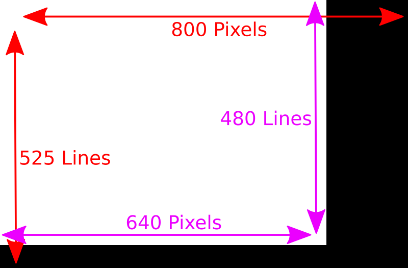
From the above image we can see that a 640x480 video signal actually generates a resolution larger than 640x480. The true resolution we generate is 800x525, but only a 640x480 portion of that signal is visible. The area that is not visible is where we generate the sync signal. In other words, every part of the above image that is black is where a sync signal is being generated.
Front Porch, Back Porch & Sync
To better understand the front porch, back porch and sync signal, let’s look at what the horizontal sync signal looks like during the duration of a line:

From this we can see that the “Front Porch” is the invisible pixels between the visible pixels and the sync pixels, and is represented by a logical one or high signal. The “Sync” is the invisible pixels between the front porch and back porch, and is represented by a logical zero or low signal. The “Back Porch” is the invisible pixels after the sync signal, and is represented by a logical one. For the case of 640x480 video, the visible pixel section lasts for 640 pixels. The front porch section lasts for 16 pixels, after which the sync signal will become a logical zero. This logical zero sync will last for 96 pixels, after which the sync signal will become a logical one again. The back porch will then last for 48 pixels. If you do a quick calculation right now of 640 + 16 + 96 + 48, we get 800 pixels which represents the full horizontal resolution of the display. The vertical sync signal works almost exactly the same, except the vertical sync signal acts on lines.
Implementation
The first thing we can do that is going to simplify a lot of the following logic is to keep track of which pixel, and which line we are on. The below code block creates two registers to keep track of the current pixel on the line (column) and the current line (line):
logic [9:0] line;
logic [9:0] column;

always @(posedge clk or posedge reset) begin
    if(reset == 1) begin
        line <= 0;
        column <= 0;
    end
    else begin
        if(column == 799 && line == 524) begin
            line <= 0;
            column <= 0;
        end
        else if(column == 799) begin
            line <= line + 1;
            column <= 0;
        end
        else begin
            column <= column + 1;
        end
    end
end
This block of Verilog works by first initializing the line and column register to zero on a reset. This is important to make sure that we start from known values, otherwise the line and column register could contain any value and our logic would not work. Next, we check if we are at the bottom of the screen by comparing the current column to 799 (the last pixel in the line) and the current line is 524 (the last line in the frame). If these conditions are both true then we reset the line and column back to zero to signify that we are starting a new frame. The next block checks if the current column equals 799. Because the above if statement failed,we know that we are at the end of the line but not the end of the frame. If this is true we increment the current line count and set the column back to zero to signify that we are starting a new line. The final block simply increments the current pixel count. If we reach this block ,we are neither at the end of the line or the end of the frame so we can simply increment to the next pixel.
Now that we are keeping track of the current column and current line, we can use this information to generate the horizontal and vertical sync signals. From the theory above we know that the sync signal is only low when we are between the front and back porch, at all other times the signal is high. From this we can generate the sync signal with an OR and two compares.
logic horizontal_sync;
logic vertical_sync;
assign horizontal_sync = column < 656 || column >= 752;
assign vertical_sync = line < 490 || line >= 492;
Let’s examine the horizontal sync signal more closely. This statement will evaluate to true if the current column is less than 656 or the current column is greater than or equal to 752. This means that the horizontal sync signal will be true except for when the current column is between 656 and 751 inclusively. That is starting on column 656 the horizontal sync signal will become false (low) and will remain that way for the next 96 pixels until we reach pixel 752 where it will return to being true (high). The vertical sync signal will work in the same way except it is turned on based on the current line. Therefore, the signal will remain high when the line is less than 490 and greater than or equal to 492, and will remain low between lines 490 and 491 inclusive.
Putting It All Together
Now that we have generated the video signal, we need to route it towards the video output connectors on the iCEBreaker 12-bit DVI Pmod. We also need to configure the iCEBreaker FPGA to have the appropriate pixel clock frequency. First to get the correct pixel clock we are going to use the following block of code:
SB_PLL40_PAD #(
  .DIVR(4'b0000),
  .DIVF(7'b1000010),
  .DIVQ(3'b101),
  .FILTER_RANGE(3'b001),
  .FEEDBACK_PATH("SIMPLE"),
  .DELAY_ADJUSTMENT_MODE_FEEDBACK("FIXED"),
  .FDA_FEEDBACK(4'b0000),
  .DELAY_ADJUSTMENT_MODE_RELATIVE("FIXED"),
  .FDA_RELATIVE(4'b0000),
  .SHIFTREG_DIV_MODE(2'b00),
  .PLLOUT_SELECT("GENCLK"),
  .ENABLE_ICEGATE(1'b0)
) usb_pll_inst (
  .PACKAGEPIN(CLK),
  .PLLOUTCORE(pixel_clock),
  .EXTFEEDBACK(),
  .DYNAMICDELAY(),
  .RESETB(1'b1),
  .BYPASS(1'b0),
  .LATCHINPUTVALUE(),
);
This block is mainly a copy paste of the PLL setup code from the iCEBreaker examples, but with a few important changes. The DIVR, DIVF, and DIVQ values are changed to create a 25.125 MHz. This is not exactly 25.175 MHz, but it is close enough that the monitor is happy enough and recognizes it as a 640x480@60 Hz signal. These values were found through the “icepll” utility, below is an example of calling this utility from the command line:
$ icepll -i 12 -o 25.175

F_PLLIN:    12.000 MHz (given)
F_PLLOUT:   25.175 MHz (requested)
F_PLLOUT:   25.125 MHz (achieved)

FEEDBACK: SIMPLE
F_PFD:   12.000 MHz
F_VCO:  804.000 MHz

DIVR:  0 (4'b0000)
DIVF: 66 (7'b1000010)
DIVQ:  5 (3'b101)

FILTER_RANGE: 1 (3'b001)
From here we can see we had an input clock of 12 MHz (This comes from the FTDI chip on the iCEBreaker board), and we wanted to get a 25.175 MHz output clock. The closest the PLL could generate was a 25.125 MHz clock with the settings provided for the DIVR, DIVF, and DIVQ values.
Now that we have a pixel clock we can wire up the necessary signals for the DVI video out. The DVI Pmod has the following mapping for all of its connectors:
| PMOD 1 | PMOD 2 | ||
| P1A1 | Red bit 4 | P1B1 | Blue bit 4 |
| P1A2 | Red bit 3 | P1B2 | Pixel clock |
| P1A3 | Green bit 4 | P1B3 | Blue bit 3 |
| P1A4 | Green bit 3 | P1B4 | Horizontal Sync |
| P1A7 | Red bit 2 | P1B7 | Blue bit 2 |
| P1A8 | Red bit 1 | P1B8 | Blue bit 1 |
| P1A9 | Green bit 2 | P1B9 | Data Enable |
| P1A10 | Green bit 1 | P1B10 | Vertical Sync |
From this we can see that we need 4 bits for each colour channel, a horizontal sync signal, a vertical sync signal, and additionally a data enable signal. The data enable signal is not part of a standard video signal and is just used by the DVI transmitter chip on the Pmod to signify when we are in visible pixel area or invisible pixel area. Therefore we will set the Date enable line when the current column is less than 640 and the current line is less than 480. Based on this we can connect the outputs like so:
logic [3:0] r;
logic [3:0] g;
logic [3:0] b;
logic data_enable;
assign data_enable = column < 640 && line < 480;
assign {P1A1,   P1A2,   P1A3,   P1A4,   P1A7,   P1A8,   P1A9,   P1A10} =
       {r[3],   r[2],   g[3],   g[2],   r[1],   r[0],   g[1],   g[0]};
assign {P1B1,   P1B2,   P1B3,   P1B4,   P1B7,   P1B8,   P1B9,   P1B10} =
       {b[3],   pixel_clock, b[2],   horizontal_sync, b[1],   b[0],   data_enable, vertical_sync};
Now for testing purposes we are going to set the output colour to be fixed to pure red so additional logic to pick a pixel colour is not required for this example. We can do this as shown below:
assign r = 4'b1111;
assign g = 4'b0000;
assign b = 4'b0000;
Putting all of the above code together with whatever additional inputs are required for the iCEBreaker FPGA gives us the following block of code:
module top
(
input CLK,
output LEDR_N,
output LEDG_N,
input BTN_N,
output P1A1, P1A2, P1A3, P1A4, P1A7, P1A8, P1A9, P1A10,
output P1B1, P1B2, P1B3, P1B4, P1B7, P1B8, P1B9, P1B10
);

`define PIXELS_PER_LINE 10'd800
`define PIXELS_VISIBLE_PER_LINE 10'd640
`define LINES_PER_FRAME 10'd525
`define LINES_VISIBLE_PER_FRAME 10'd480
`define HORIZONTAL_FRONTPORCH 10'd656
`define HORIZONTAL_BACKPORCH 10'd752
`define VERTICAL_FRONTPORCH 10'd490
`define VERTICAL_BACKPORCH 10'd492

logic [9:0] line;
logic [9:0] column;
logic horizontal_sync;
logic vertical_sync;
logic data_enable;
logic pixel_clock;
logic reset;

logic [3:0] r;
logic [3:0] g;
logic [3:0] b;

assign horizontal_sync = column < (`HORIZONTAL_FRONTPORCH) || column >= (`HORIZONTAL_BACKPORCH);
assign vertical_sync = line < (`VERTICAL_FRONTPORCH) || line >= (`VERTICAL_BACKPORCH);
assign data_enable = (column < `PIXELS_VISIBLE_PER_LINE) && (line < `LINES_VISIBLE_PER_FRAME);

assign reset = ~BTN_N;
assign LEDR_N = 1;
assign LEDG_N = 1;

assign r = 4'b1111;
assign g = 4'b0000;
assign b = 4'b0000;

assign {P1A1,   P1A2,   P1A3,   P1A4,   P1A7,   P1A8,   P1A9,   P1A10} =
       {r[3],   r[2],   g[3],   g[2],   r[1],   r[0],   g[1],   g[0]};
assign {P1B1,   P1B2,   P1B3,   P1B4,   P1B7,   P1B8,   P1B9,   P1B10} =
       {b[3],   pixel_clock, b[2],   horizontal_sync, b[1],   b[0],   data_enable, vertical_sync};

// Pixel and line counter
always @(posedge pixel_clock or posedge reset) begin
    if(reset == 1) begin
        line <= `LINES_PER_FRAME - 2;
        column <= `PIXELS_PER_LINE - 16;
    end
    else begin
        if(column == (`PIXELS_PER_LINE - 1) && line == (`LINES_PER_FRAME - 1)) begin
            line <= 0;
            column <= 0;
        end
        else if(column == `PIXELS_PER_LINE - 1) begin
            line <= line + 1;
            column <= 0;
        end
        else begin
            column <= column + 1;
        end
    end
end

SB_PLL40_PAD #(
  .DIVR(4'b0000),
  .DIVF(7'b1000010),
  .DIVQ(3'b101),
  .FILTER_RANGE(3'b001),
  .FEEDBACK_PATH("SIMPLE"),
  .DELAY_ADJUSTMENT_MODE_FEEDBACK("FIXED"),
  .FDA_FEEDBACK(4'b0000),
  .DELAY_ADJUSTMENT_MODE_RELATIVE("FIXED"),
  .FDA_RELATIVE(4'b0000),
  .SHIFTREG_DIV_MODE(2'b00),
  .PLLOUT_SELECT("GENCLK"),
  .ENABLE_ICEGATE(1'b0)
) usb_pll_inst (
  .PACKAGEPIN(CLK),
  .PLLOUTCORE(pixel_clock),
  .EXTFEEDBACK(),
  .DYNAMICDELAY(),
  .RESETB(1'b1),
  .BYPASS(1'b0),
  .LATCHINPUTVALUE(),
);

endmodule
To build this, you will require a .pcf file describing the pin mapping of the iCEBreaker board. I grabbed mine from the iCEBreaker examples here. Grab that file and put it in the same folder as the file for the code provided above. We can the run the following commands to generate a binary to program onto the FPGA:
yosys -ql out.log  -p 'synth_ice40 -top top -json out.json' top.sv
nextpnr-ice40 --up5k   --json out.json --pcf icebreaker.pcf --asc out.asc
icetime  -d up5k -mtr out.rpt out.asc
icepack out.asc out.bin
This will generate an out.bin file that we will need to flash onto the board. Make sure your iCEBreaker FPGA is connected via USB to your computer and you can program it with the following commands.
iceprog out.binNow connect up a video cable (my DVI Pmod has an HDMI connector, but it only carries the DVI video signal) to the board and monitor and you should get results like this:
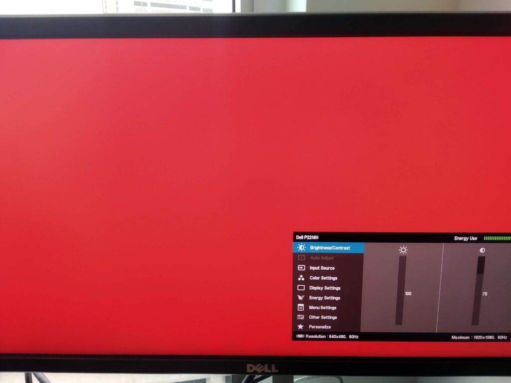
You can also see from the monitor settings menu that the video signal was recognized as 640x480@60 Hz. Now the code presented in this post is specific to the iCEBreaker board and the DVI Pmod, but the theory can be applied to any FPGA and any connector that uses a video signal like this. For example you could wire up a DAC with a resistor ladder to generate a VGA signal. The logic for the timings here would be exactly the same if you wanted a 640x480@60 Hz VGA signal.